-
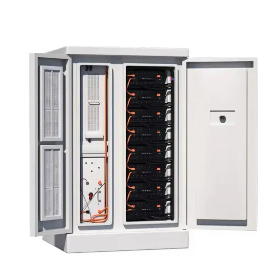
Photovoltaic vanadium battery energy storage principle diagram
Home » Vanadium Energy Storage » How-a-Vanadium-Redox-Battery. Home » Vanadium Energy Storage » How-a-Vanadium-Redox-Battery. Redox flow batteries (RFBs) store energy in two tanks that are separated from the cell stack (which converts chemical energy to electrical energy, or vice versa). This design enables the Figure 1 illustrates the flow battery concept. VRFB was ch rged by a solar power supply system which supplies electricity to residential loads. This approach offers interesting solutions for low-cost energy storage, load leveling and power peak shaving. . on requirements increases in order to avoid shortfalls in coverage. The various transport and kinetic p chemical species are stored outside the cell. The power each cell generat s depends on the current. . The vanadium redox battery (VRB), also known as the vanadium flow battery (VFB) or vanadium redox flow battery (VRFB), is a type of rechargeable flow battery which employs vanadium ions as charge carriers.
[PDF Version]
-
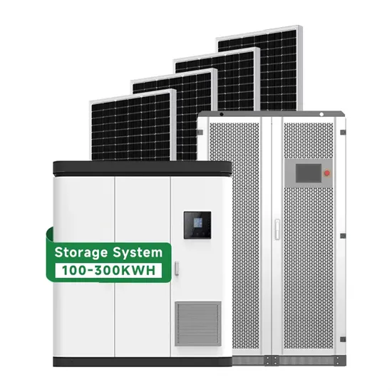
Photovoltaic energy storage power station working principle diagram
This guide offers professional guidance on the principles, components, and key points of the circuit connection in a PV system with storage. . A solar energy storage system diagram is the foundational roadmap for any successful solar power installation. . Photovoltaic power plants convert sunlight directly into electricity using solar cells, while concentrated solar power plants use mirrors or lenses to concentrate sunlight and heat a fluid that drives a turbine or engine. A detailed design scheme of the system architecture and energy storage capacity is proposed,which is applied to the design and optimization of he electrochemical energy storage. . Solar power is becoming an increasingly popular alternative energy source, and understanding the schematic diagram of a solar power plant is essential for anyone interested in harnessing this renewable energy. When installed at site,solar modules are wired together in series to form strin s.
[PDF Version]
-
Diagram of installation method of row photovoltaic bracket
Fix photovoltaic panels to the beams using fasteners. Column specifications: 60mm diameter, 3mm. . Three-row photovoltaic bracket installation diagram Three-row photovoltaic bracket installation diagram Can a 3 phase inverter be installed vertically? The inverter is typically mounted vertically, and the instructions in this section are applicable for vertical installation. The POWER RAIL mounting system is designed ard Rail 1 kit will cover 2 PV panelswithin a ro.
[PDF Version]
-
Mini photovoltaic glue board size diagram
Drag and drop components, connect lines, and save your work. . he section for more details on implementing MPPT. A common MPP voltage range for PV modules can be defined in the range of 25V to 45V,at a power genera-tion of approx mate 250W,with an open circuit voltage below 50V. A high-level block diagram of a grid-connecte solar microinverter system is shown. . Meta Description: Discover the critical specifications and dimensions of photovoltaic glue boards with technical data tables, real-world case studies, and 2023 installation guidelines. With solar installations increasing by 34%. . Solar Panel Glue Board 58*38 2V 130MA Mini Solar Panel Lamp Charging Power Generation Small Production Solar Panel Glue Board Overview: This Solar Panel Glue Board, model AK5838, is a compact and efficient photovoltaic solution designed for various applications. Available at a lower price from ot e sticks at low cost wholesale prices. Through cutting solar cells into small pieces to meet different. . he standard 156 mm wafer size to larger wafer sizes. Although a range of cell sizes are under development,some sizes have emerged as the new indus e discussed to achieve stable and efficient SC-PSCs. The structural disorder,large grain boundaries,and significantly high defect density within. . © 2025 - 2026 Solar Diagram Tool. A free online tool to easily create, customize, and export professional solar power system diagrams.
[PDF Version]
-

Flat roof photovoltaic panel effect diagram
The following diagram illustrates the side view of a tilted solar panel, showing the vertical height of the top edge and the concept of row spacing: This geometry explains why taller panels require more spacing and how shading is controlled by correct layout design. . hading area higher than that in the unshaded area. This is because the photovoltaic panels store a certain amount of heat during the day when the irradiation is abundant,radiating heat with the sha ing area at night,causing its temperature to r d heat and mass transfer model to solar radiation. Site Assessment Load Capacity: Verify roof structural integrity. . What is a solar panel layout plan? A solar panel layout plan is a detailed design or diagram that shows how and where solar panels are to be placed on a roof. . Besides energy generation,a roof-added PV system affects the building's energy consumption due to its shading effect.
[PDF Version]
-
Solar inverter activation process diagram
Meta Description: Discover the critical photovoltaic inverter startup sequence diagram with data-backed protocols, common installation errors, and real-world case studies to optimize your solar system's performance. Why Proper Startup Sequence Matters for Photovoltaic. . Reorient or relocate the receiving antenna. Consult the dealer or an experienced radio/TV technician for help. A solar power inverter circuit diagram is a crucial component of a solar power system that enables the conversion of DC output from solar panels into AC. . of electronics, power systems, and solar energy.
[PDF Version]