-
Ulaanbaatar has a communication base station inverter connected to the grid
Thus, unlike the off-grid systems, you will connect the inverter directly to the grid. Plug it into the main power switchboard to join the grid, which acts as the input wire. . The EES operates based on a CHP plant with a capacity of 36 MW to supply electricity to consumers in Dornod and Sukhbaatar provinces and the Sukhbaatar branch of the EES is connected to the CES by a 110 kV OHL. The SES is connected to the CES by 110 kV and 220kV OHLs, and the Dalanzadgad CHP with a. . Department of Green Energy and Engineering, National University of Mongolia, Ulaanbaatar 14201, Mongolia Department of Integrated Energy and Infra System, Kangwon National University, Chuncheon-si 24341, Republic of Korea Author to whom correspondence should be addressed. Adopting and widely. . How does a power station inverter work? As an important component of the entire power station, the inverter is connected to the DC components at the top and the grid-connected equipment at the bottom.
[PDF Version]
-
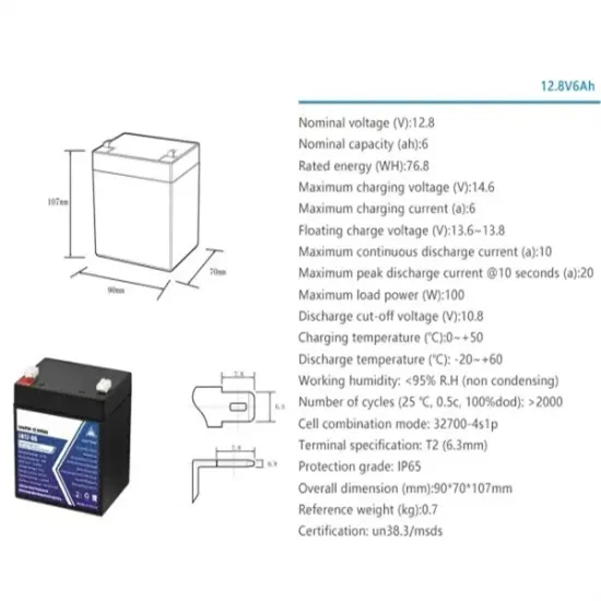
The battery strength of the communication base station inverter connected to the grid refers to
The strength of the grid is defined by the short circuit ratio (SCR), which is the ratio of the short circuit power at the point of common coupling (PCC) and the rated power of the inverter. When the SCR is below 6–10, the grid is weak. Battery energy storage system (BESS) has been applied extensively to provide grid services such as frequency regulation, voltage. . Hybrid inverters adeptly manage multiple energy inputs, including solar photovoltaic (PV) arrays, battery banks, the utility grid (if available), and backup generators. This capability is paramount for BTS shelters, where power reliability is non-negotiable. And while diesel generators are still in use, they come with high fuel costs, maintenance burdens, and. . The integration of battery energy storage systems with photovoltaic systems to form renewable microgrids has become more practical and reliable, but designing these systems involves complexity and relies on connection standards and operational requirements for reliable and safe grid-connected. .
[PDF Version]
-
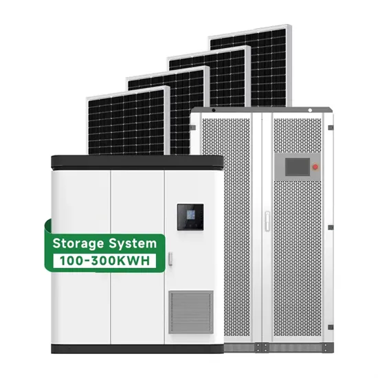
Calculation of the size of the circuit breaker for the solar container communication station inverter
Find the minimum breaker size needed for your load, applying the NEC 125% continuous load rule for safety. Formula: Breaker Amps = Load W ÷ Voltage × (1. Rounded up to nearest standard breaker size. NEC requires 125% of continuous. . EG4 ELECTRONICS Electrical Breakers Sizing provides technical information to help users determine the correct breaker type and size for inverters, batteries, and solar panels. It covers breaker use cases (PV DC, Charge Controller DC, Inverter AC), operation principles (thermal and electromagnetic. . The appropriate fuse or circuit breaker size depends on multiple factors, including application scenario, system capacity, and additional considerations. Here's what it helps you accomplish: 1. A solar PV system has several key parts, each needing its own circuit breaker. System Capacity: The overall electrical capacity of the system plays a. .
[PDF Version]
-
Solar inverter dcdc boost circuit
This guide details how to implement a digitally controlled DC-DC converter that is used as a front-end converter for solar inverter (DC-AC) application. This converter implements an isolated DC-DC stage with maximum power point tracking (MPPT) algorithm to use the full capacity of a 500-W solar. . ABSTRACT--- This paper presents a new ideology called as boost inverter which converts input DC supply into AC directly without using any filter circuit. The boosting of voltage can be done by low operating voltage. The input to. . MPPT is the abbreviation of Maximum Power Point Tracking. As a vital function of the solar inverter, MPPT not only effectively raises the radiation utilization rate and maximizes the solar inverter's working efficiency but also converts voltage and currents output by modules to adjust their power. . This design is a digitally-controlled, solar DC/DC converter with maximum power point tracking (MPPT), for use in central or string solar inverters.
[PDF Version]
-
Solar inverter activation process diagram
Meta Description: Discover the critical photovoltaic inverter startup sequence diagram with data-backed protocols, common installation errors, and real-world case studies to optimize your solar system's performance. Why Proper Startup Sequence Matters for Photovoltaic. . Reorient or relocate the receiving antenna. Consult the dealer or an experienced radio/TV technician for help. A solar power inverter circuit diagram is a crucial component of a solar power system that enables the conversion of DC output from solar panels into AC. . of electronics, power systems, and solar energy.
[PDF Version]
-
Solar inverter wiring effect diagram
Photovoltaic inverter layout wiring diagra fferent components of a solar power system. A solar inverter is a device that converts the direct current (DC) electricity generated by solar panels into alternating current (AC) electricity that can be used. . Solar inverter wiring is a crucial part of any solar energy system as it connects the solar panels, inverters, batteries, and other components so that you can ensure the efficient conversion of solar energy into usable electricity. Before hooking your solar panels up to an inverter, however. .
[PDF Version]