-
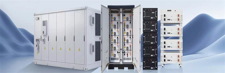
Liquid cooling energy storage box structure diagram
ure 1: Schematic diagram of EIA liquid cooled cabinet. High integration, integrating liquid cooling related components into a standard iquid nitrogen, and two- m, power system coupling and grid inte ide, Intel has selected Stulz* liquid cooling products. . Outdoor liquid cooled and air cooled cabinets can be paired togetherutilizing a high voltage/current battery combiner box. Outdoor cabinets are manufactured to be a install ready and cost effective part of the total on-grid,hybrid,off-grid commercial/industrial or utility scale battery energy. . Who makes energy storage enclosures?Machan offers comprehensive solutions for the manufacture of energy storage enclosures. This article explores how these systems optimize battery performance, enhance safety, and support sustainable energy storage across industries. 016MWh battery compartment utilizes a battery cluster with a rated voltage of 1331. The liquid cooling piping runs along the bottom of the cabin,while. . natural gas (LNG) purification cold box. 5MW/5MWh energy storage system with a non-walk-in design which facilitates equipment installation and maintenance, while ensuring long-term safe and reliable operation of the entire storage system.
[PDF Version]
-
Photovoltaic energy storage hydrogen energy structure diagram
The PV power generation and hydrogen production hybrid energy storage system includes PV power generation system, electrolytic water hydrogen production, hydrogen storage tank, energy storage system, and other subsystems. The system structure . . to perform PV-H 2 design for different hybrid configurations. However, the inherent intermittent and random characteristics of solar energy reduce the efficiency of hydrogen production. A detailed design scheme of the system architecture and energy storage capacity is proposed,which is applied to the design and optimization of he electrochemical energy storage system of photovoltaic power st cooperate with. . g hydrogen using solar energy as a catalyst. The two commonly recognised cat gories of processes are direct and indirect. Due to the indirect processes low efficiency, excessive heat dissipation, and dearth of readily available heat-resistant materials, they are ranked lower than the direct the. . As a case study on sustainable energy use in educational institutions, this study examines the design and integration of a solar–hydrogen storage system within the energy management framework of Kangwon National University's Samcheok Campus.
[PDF Version]
-
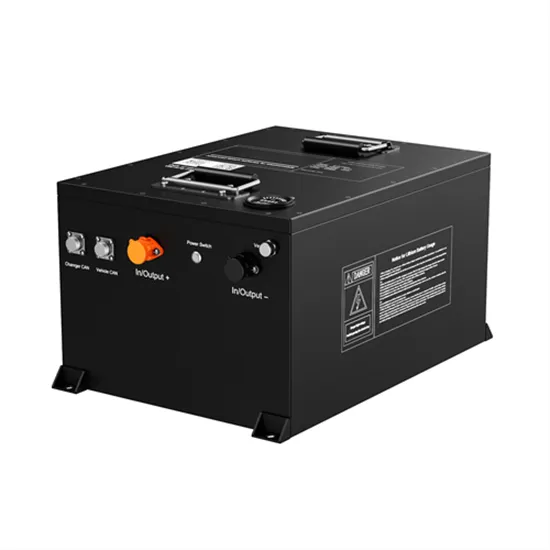
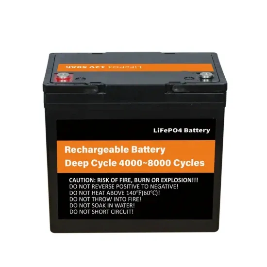
Energy storage lithium battery material structure diagram
Structure diagram of energy storage li n together to store and release energy efficiently. The diagram typically includes the following key components: Anode: This is the negative electrode of the battery where lit ium ions are released during t. Intercalation refers to the insertion of lithium ions into the crystal or molecular structure of the electrode material. Cathode active materials are the source of lithium-ions and anode active materials host lithium-ions during the charged state. It is essential that the electrode materials can. . Lithium-ion batteries are the dominant electrochemical grid energy storage technology because of their extensive development history in consumer products and electric vehicles. LFP: lithium-ironphosphate; NMC: nickel-manganese- chargeable batteri ation projects and accelerated the energy transition. l role in balancin an anode, a cathode, an electrolyte, and a separator. Learn how advanced designs enhance efficiency and reliability across industries like renewable energy and EVs.
[PDF Version]
-
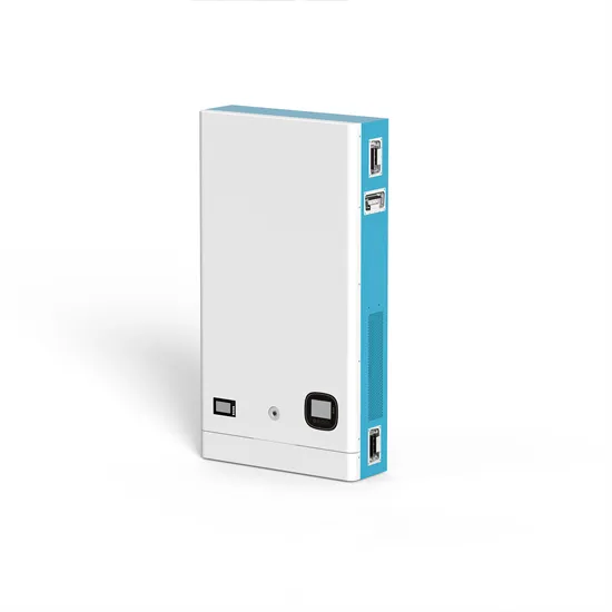
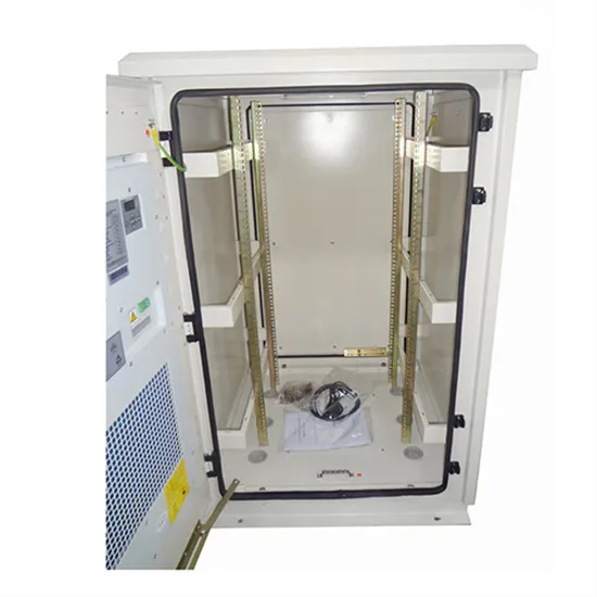
Photovoltaic structure inside the energy storage cabinet
Summary: This article explores the latest patent advancements in photovoltaic energy storage cabinet design, focusing on modularity, safety, and efficiency. Learn how these innovations address global renewable energy challenges and discover real-world applications driving the solar storage market. . A solar energy storage system diagram is the foundational roadmap for any successful solar power installation. These modular powerhouses are revolutionizing how w have more components than a PV-direct system. This fact sheet will present the difer storage technologies feasible for microgrids?. This article is a comprehensive, engineering-grade explanation of BESS cabinets: what they are, how they work, what's inside (including HV BOX), how to size them for different applications (not only arbitrage), and how to choose between All-in-One vs battery-only, as well as DC-coupled vs. . Step inside our energy storage inverters and see how they are built to last. This video walks you through the internal structure, from the power units to the. . What is a photovoltaic grid-connected cabinet? Photovoltaic grid-connected cabinet is a distribution equipment connecting photovoltaic power station and power grid,and is the total outgoing of photovoltaic power station in the photovoltaic power generation system,and its main role is to act as the. .
[PDF Version]
-
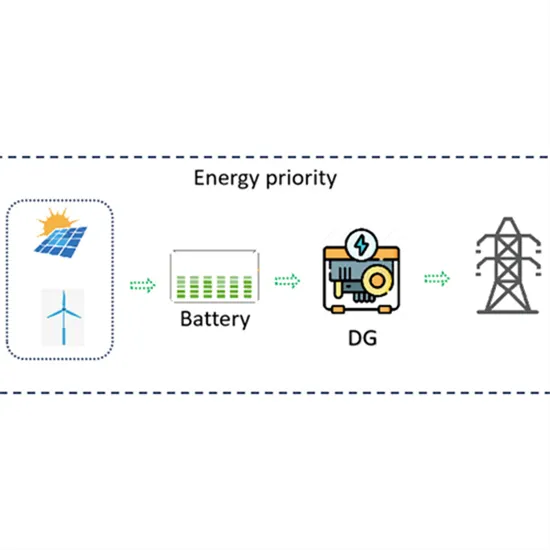
Photovoltaic energy storage power station working principle diagram
This guide offers professional guidance on the principles, components, and key points of the circuit connection in a PV system with storage. . A solar energy storage system diagram is the foundational roadmap for any successful solar power installation. . Photovoltaic power plants convert sunlight directly into electricity using solar cells, while concentrated solar power plants use mirrors or lenses to concentrate sunlight and heat a fluid that drives a turbine or engine. A detailed design scheme of the system architecture and energy storage capacity is proposed,which is applied to the design and optimization of he electrochemical energy storage. . Solar power is becoming an increasingly popular alternative energy source, and understanding the schematic diagram of a solar power plant is essential for anyone interested in harnessing this renewable energy. When installed at site,solar modules are wired together in series to form strin s.
[PDF Version]
-
Photovoltaic vanadium battery energy storage principle diagram
Home » Vanadium Energy Storage » How-a-Vanadium-Redox-Battery. Home » Vanadium Energy Storage » How-a-Vanadium-Redox-Battery. Redox flow batteries (RFBs) store energy in two tanks that are separated from the cell stack (which converts chemical energy to electrical energy, or vice versa). This design enables the Figure 1 illustrates the flow battery concept. VRFB was ch rged by a solar power supply system which supplies electricity to residential loads. This approach offers interesting solutions for low-cost energy storage, load leveling and power peak shaving. . on requirements increases in order to avoid shortfalls in coverage. The various transport and kinetic p chemical species are stored outside the cell. The power each cell generat s depends on the current. . The vanadium redox battery (VRB), also known as the vanadium flow battery (VFB) or vanadium redox flow battery (VRFB), is a type of rechargeable flow battery which employs vanadium ions as charge carriers.
[PDF Version]