-
Energy storage container air duct design specifications
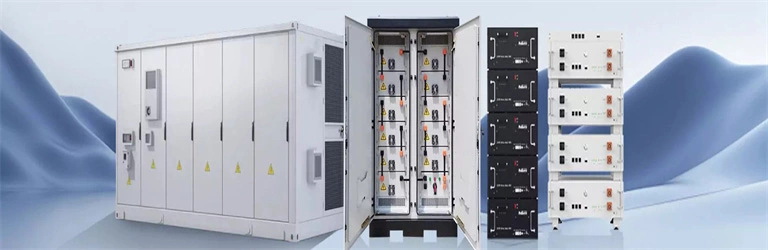
Air duct design refers to how airflow is organized inside an energy storage cabinet to control the temperature of lithium iron phosphate (LFP) battery modules. In an air-cooled system, the design ensures steady airflow across batteries, avoiding overheating and. . The containerized energy storage battery system studied in this paper is derived from the "120TEU pure battery container ship" constructed by Wuxi Silent Electric System Technology Co. Both system noise and noise at the air outlet are important omfort considerations in the air distribution system y limiting the accumulation of hydrogen in the battery room. The ventilation system includes an air conditioner, an air duct, and multiple columns of battery racks, and each battery rack includes multiple lines of battery boxes. . Optimal in-PACK duct design, achieve high-efficient cooling and low energy consumption. SPECIFICATIONS-Air Cooling Energy Storage System.
[PDF Version]
-
Liquid cooling energy storage box structure diagram
ure 1: Schematic diagram of EIA liquid cooled cabinet. High integration, integrating liquid cooling related components into a standard iquid nitrogen, and two- m, power system coupling and grid inte ide, Intel has selected Stulz* liquid cooling products. . Outdoor liquid cooled and air cooled cabinets can be paired togetherutilizing a high voltage/current battery combiner box. Outdoor cabinets are manufactured to be a install ready and cost effective part of the total on-grid,hybrid,off-grid commercial/industrial or utility scale battery energy. . Who makes energy storage enclosures?Machan offers comprehensive solutions for the manufacture of energy storage enclosures. This article explores how these systems optimize battery performance, enhance safety, and support sustainable energy storage across industries. 016MWh battery compartment utilizes a battery cluster with a rated voltage of 1331. The liquid cooling piping runs along the bottom of the cabin,while. . natural gas (LNG) purification cold box. 5MW/5MWh energy storage system with a non-walk-in design which facilitates equipment installation and maintenance, while ensuring long-term safe and reliable operation of the entire storage system.
[PDF Version]
-
Energy storage cabinet battery rack air duct requirements
Ventilation systems must limit hydrogen to below 25% of its lower flammable limit—about 1% concentration—or provide a minimum airflow of 1 cubic foot per minute per square foot of floor space. . Each room, locker, and box for storage batteries must be arranged or ventilated to prevent accumulation of flammable gas. If power ventilation is required, the following must be met: (1) The power ventilation system must be separate from ventilation systems for other spaces. To ensure your system operates safely and efficiently, proper installation is paramount. This involves more than just connecting wires; it requires careful attention to ventilation and clearance. Hydrogen release is a normal part of the charging process, but trouble arises when the flammable gas becomes concentrated enough to create an explosion risk — which is why. . High-density battery rack installations require mechanical ventilation to control hydrogen gas buildup and maintain safety.
[PDF Version]
-
Photovoltaic energy storage hydrogen energy structure diagram
The PV power generation and hydrogen production hybrid energy storage system includes PV power generation system, electrolytic water hydrogen production, hydrogen storage tank, energy storage system, and other subsystems. The system structure . . to perform PV-H 2 design for different hybrid configurations. However, the inherent intermittent and random characteristics of solar energy reduce the efficiency of hydrogen production. A detailed design scheme of the system architecture and energy storage capacity is proposed,which is applied to the design and optimization of he electrochemical energy storage system of photovoltaic power st cooperate with. . g hydrogen using solar energy as a catalyst. The two commonly recognised cat gories of processes are direct and indirect. Due to the indirect processes low efficiency, excessive heat dissipation, and dearth of readily available heat-resistant materials, they are ranked lower than the direct the. . As a case study on sustainable energy use in educational institutions, this study examines the design and integration of a solar–hydrogen storage system within the energy management framework of Kangwon National University's Samcheok Campus.
[PDF Version]
-
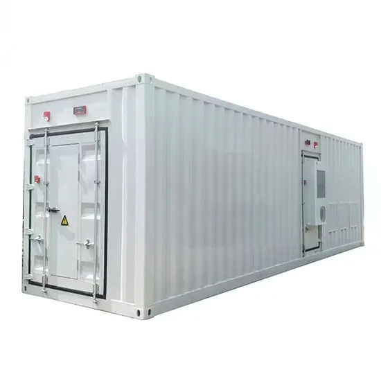
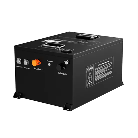
Solar container lithium battery energy storage power supply structure
Containerized battery energy storage system integrates lithium-ion batteries, battery management system, AC/DC conversion device, thermal management system, and fire protection system in a standard container, which has the advantages of high integration, small occupation area . . Containerized battery energy storage system integrates lithium-ion batteries, battery management system, AC/DC conversion device, thermal management system, and fire protection system in a standard container, which has the advantages of high integration, small occupation area . . Mitsubishi Heavy Industries, Ltd. (MHI) has been developing a large-scale energy storage system (ESS) using 50Ah-class P140 lithium-ion batteries that we developed. This report will describe the development status and application examples. Want to learn more. . The battery is a crucial component within the BESS; it stores the energy ready to be dispatched when needed. It integrates battery cabinets, lithium battery management system (BMS), container dynamic loop monitoring system, and energy storage converters and energy management. . ers lay out low-voltage power distribution and conversion for a b de ion – and energy and assets monitoring – for a utility-scale battery energy storage system entation to perform the necessary actions to adapt this reference design for the project requirements. ABB can provide support during all. .
[PDF Version]
-
Energy storage lithium battery material structure diagram
Structure diagram of energy storage li n together to store and release energy efficiently. The diagram typically includes the following key components: Anode: This is the negative electrode of the battery where lit ium ions are released during t. Intercalation refers to the insertion of lithium ions into the crystal or molecular structure of the electrode material. Cathode active materials are the source of lithium-ions and anode active materials host lithium-ions during the charged state. It is essential that the electrode materials can. . Lithium-ion batteries are the dominant electrochemical grid energy storage technology because of their extensive development history in consumer products and electric vehicles. LFP: lithium-ironphosphate; NMC: nickel-manganese- chargeable batteri ation projects and accelerated the energy transition. l role in balancin an anode, a cathode, an electrolyte, and a separator. Learn how advanced designs enhance efficiency and reliability across industries like renewable energy and EVs.
[PDF Version]