-
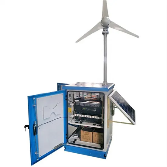
Photovoltaic energy storage hydrogen energy structure diagram
The PV power generation and hydrogen production hybrid energy storage system includes PV power generation system, electrolytic water hydrogen production, hydrogen storage tank, energy storage system, and other subsystems. The system structure . . to perform PV-H 2 design for different hybrid configurations. However, the inherent intermittent and random characteristics of solar energy reduce the efficiency of hydrogen production. A detailed design scheme of the system architecture and energy storage capacity is proposed,which is applied to the design and optimization of he electrochemical energy storage system of photovoltaic power st cooperate with. . g hydrogen using solar energy as a catalyst. The two commonly recognised cat gories of processes are direct and indirect. Due to the indirect processes low efficiency, excessive heat dissipation, and dearth of readily available heat-resistant materials, they are ranked lower than the direct the. . As a case study on sustainable energy use in educational institutions, this study examines the design and integration of a solar–hydrogen storage system within the energy management framework of Kangwon National University's Samcheok Campus.
[PDF Version]
-
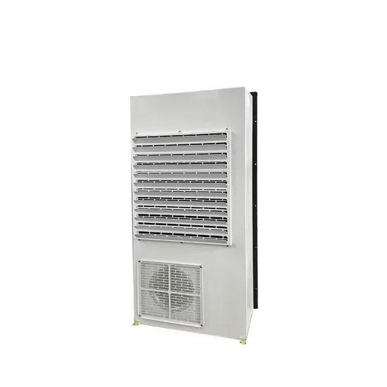
Liquid cooling energy storage box structure diagram
ure 1: Schematic diagram of EIA liquid cooled cabinet. High integration, integrating liquid cooling related components into a standard iquid nitrogen, and two- m, power system coupling and grid inte ide, Intel has selected Stulz* liquid cooling products. . Outdoor liquid cooled and air cooled cabinets can be paired togetherutilizing a high voltage/current battery combiner box. Outdoor cabinets are manufactured to be a install ready and cost effective part of the total on-grid,hybrid,off-grid commercial/industrial or utility scale battery energy. . Who makes energy storage enclosures?Machan offers comprehensive solutions for the manufacture of energy storage enclosures. This article explores how these systems optimize battery performance, enhance safety, and support sustainable energy storage across industries. 016MWh battery compartment utilizes a battery cluster with a rated voltage of 1331. The liquid cooling piping runs along the bottom of the cabin,while. . natural gas (LNG) purification cold box. 5MW/5MWh energy storage system with a non-walk-in design which facilitates equipment installation and maintenance, while ensuring long-term safe and reliable operation of the entire storage system.
[PDF Version]
-
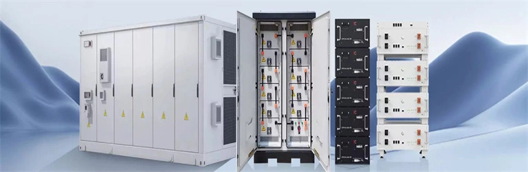
Energy storage system structure diagram
Designing a Battery Energy Storage System (BESS) container enclosure requires a comprehensive understanding of several key factors. This guide provides an in-depth look at these considerations, helping you navigate. Page 1/4 Structural diagram of energy . . ers lay out low-voltage power distribution and conversion for a b de ion – and energy and assets monitoring – for a utility-scale battery energy storage system entation to perform the necessary actions to adapt this reference design for the project requirements. Analogously, the architecture of a building is the design of the essential structure, including beams, walls, floors, and infra tructure, underneath its outer skin. In recent years, with the rapid development of MW-level battery energy storage technology at home and. . Energy storage systems act as the bridge between erratic renewable supply and steady demand—but only if designed correctly. Every energy storage primary diagram reveals three non-negotiable components: Take Tesla's Megapack installations—their diagrams show liquid-cooled battery racks connected to. .
[PDF Version]
-
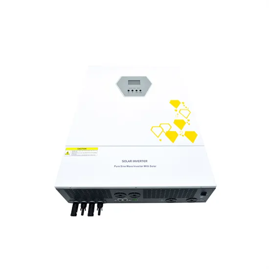
Energy storage pcs system design
This article explains the working principles of PCS in a clear, accessible way while highlighting common configuration mistakes in real-world applications, helping readers better understand and optimize energy storage system designs. How Does PCS Work?. Our integrated circuits and reference designs help you create a smarter and more efficient power conversion system (PCS) that sits between the grid or PV panels and the energy storage battery packs. This chapter describes the basics of power. . Power conversion systems (PCS) are intermediary devices between the storage element, such as large banks of (DC) batteries, and the (AC) power grid With the enormous amount of energy being consumed and government policies to minimize carbon emissions, the shift to renewable energy makes reliably. . PCS is a high power density power conversion system for utility-scale battery energy storage systems (up to 1500 VDC).
[PDF Version]
-
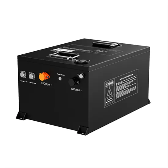
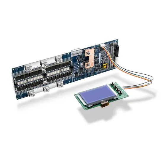
Korean lithium battery energy storage system design
Summary: Busan, South Korea, is fast becoming a critical player in manufacturing lithium battery components for energy storage systems. This article explores the city's industrial advantages, emerging trends in renewable energy storage, and how local. . Busan's BMS manufacturers combine military-grade safety standards with modular designs adaptable to: After implementing Busan BMS in offshore energy storage systems, EK SOLAR achieved: Q: How does BMS improve battery lifespan? A: Through active cell balancing and temperature control Q: Can existing. . The South Korean lithium battery energy storage system (ESS) market has experienced robust growth driven by escalating demand across renewable energy integration, grid stabilization, and industrial applications. As of recent valuations, the market is estimated to generate several billion USD in. . We enable and respect our talents. the way to a more sustainable environment, society and governance. . Electricity storage can play a significant role in modern decarbonized energy systems by enabling a time-delayed use of electricity. Leveraging both human insight and AI-powered analysis, KORE Power's asset management platform goes well beyond simple energy. .
[PDF Version]
-

Design standards for energy storage high-voltage boxes
Summary: This article explores critical design principles for high voltage boxes in modern energy storage systems, addressing safety, efficiency, and integration challenges. Discover how advanced components and intelligent monitoring solutions are reshaping this crucial. . rgy Storage System (BESS) connected to a grid-connected PV system. It provides info following system functions:BESS as backupOffsetting peak loadsZero exportThe batte y in the BESS is charged either from the PV dustry pro essionals indicate a significant need for standards. What is. . Design standard atlas of en DC and feeding it forward to the high voltage battery. It is an IEC 61508 and IEC 60730 compliant architecture of up to 1500 V intended for a variety of high-voltage battery management solutions for utility, commercial, industrial and residential energy storage.
[PDF Version]