-
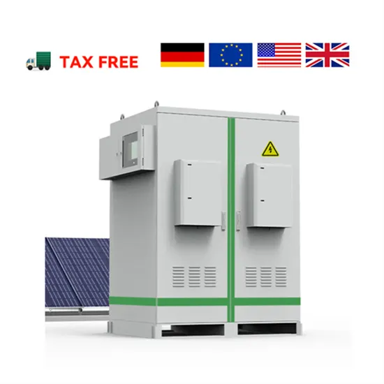
Diagram of DC line connection under photovoltaic panel
Detailed Diagram: Shows each conductor, junction, and termination point for precise installation guidance. Creating compliant PV wiring diagrams is a step-by-step process that transforms raw design data into a clear, permit-ready document. . The single most important tool in your arsenal is a solar panel wiring diagram. This is your non-negotiable blueprint, a detailed map that ensures every component works together safely and efficiently. This definitive guide will cover everything from the core wiring methods to critical safety. . According to NREL's SolarAPP+ Performance Review, projects submitted with compliant and clearly documented electrical diagrams—verified through automated review—were approved 13 business days faster, eliminating over 134,000 business-days of permitting delays across participating jurisdictions. So. . The easiest way to draw electrical diagrams for photovoltaic installations is by using the EasySolar app, where such diagrams, including all necessary components, can be automatically generated. There's no such thing as a single correct diagram — several wiring configurations can produce the same. . An effective solar panel wiring is highly essential for maximum energy output, solar power system stability and preventing power loss.
[PDF Version]
-
Photovoltaic panel column welding method diagram
straightforward wiring diagram and step-by-step guide. Wiring a 12V solar panel typically involves connecting the e installation and maintenance of solar panel systems. These diagrams provide a vi ual representation of how the panels are connec allation, including the components and steps. . Welding photovoltaic solar column feet requires expertise to ensure structural integrity and longevity. Precision in welding techniques is imperative for the functionality of solar installations, 2. Specific materials such as steel or aluminum must be selected for the column feet, 3. This thickn ss t structure system with a beam-column. . Summary: Discover professional techniques for welding roof photovoltaic panels, including step-by-step installation methods, industry best practices, and data-backed insights. These include improper angle, lack of edge, and the poor state of the welding belt. Mechanical connectors can be mounted to a module or racking frame with lay-in features which accept a copper wi e that bonds and grounds components, said Zwit.
[PDF Version]
-
Photovoltaic panel installation connection diagram
In this guide, we'll walk through how to design your wiring layout, the essential components you'll need, and how to interpret or create diagrams for both grid-tied and off-grid systems. . The single most important tool in your arsenal is a solar panel wiring diagram. This is your non-negotiable blueprint, a detailed map that ensures every component works together safely and efficiently. Schematics is one of the more technical parts of DIY solar, but it doesn't have to feel like. . Read on to find out more about solar panel connection diagrams and how to wire PV modules to achieve the best performance based on your unique installation requirements. Most modern photovoltaic systems for residential or portable use don't actually require much “wiring.
[PDF Version]
-
Photovoltaic panel landing effect diagram
Let's visualize the photoelectric effect process through a typical photovoltaic schematic: When photons hit the panel, they create electron-hole pairs. The electric field at the p-n junction then drives these charges apart - that's your DC electricity starting to flow. . The photovoltaic effect is a process that generates voltage or electric current in a photovoltaic cell when it is exposed to sunlight. That is why many solar angles are used in PV power calculations, and solar tracking systems improve the efficiency of PV panels by following the sun through the sky. 1) provides a demonstration of the band gap concept. Whether you're a homeowner considering solar. . An Ntype semiconductor has electrons as majority charge carriers. Similarly, the negatives at the N-side gain positive. .
[PDF Version]
-
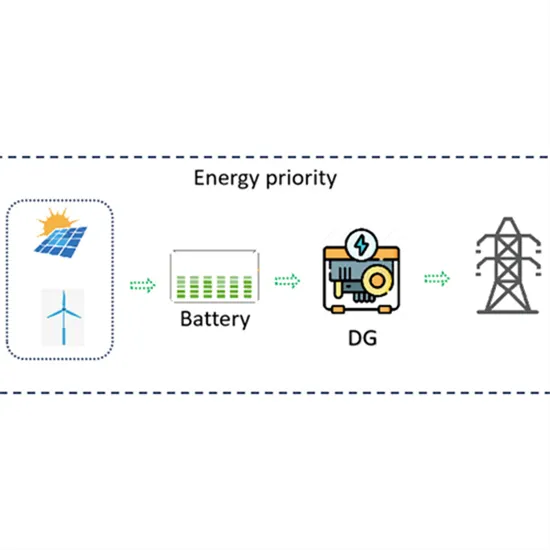
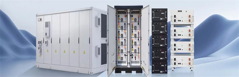
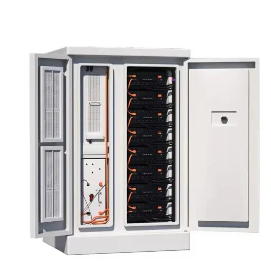
Photovoltaic energy storage power station working principle diagram
This guide offers professional guidance on the principles, components, and key points of the circuit connection in a PV system with storage. . A solar energy storage system diagram is the foundational roadmap for any successful solar power installation. . Photovoltaic power plants convert sunlight directly into electricity using solar cells, while concentrated solar power plants use mirrors or lenses to concentrate sunlight and heat a fluid that drives a turbine or engine. A detailed design scheme of the system architecture and energy storage capacity is proposed,which is applied to the design and optimization of he electrochemical energy storage. . Solar power is becoming an increasingly popular alternative energy source, and understanding the schematic diagram of a solar power plant is essential for anyone interested in harnessing this renewable energy. When installed at site,solar modules are wired together in series to form strin s.
[PDF Version]
-
Mini photovoltaic glue board size diagram
Drag and drop components, connect lines, and save your work. . he section for more details on implementing MPPT. A common MPP voltage range for PV modules can be defined in the range of 25V to 45V,at a power genera-tion of approx mate 250W,with an open circuit voltage below 50V. A high-level block diagram of a grid-connecte solar microinverter system is shown. . Meta Description: Discover the critical specifications and dimensions of photovoltaic glue boards with technical data tables, real-world case studies, and 2023 installation guidelines. With solar installations increasing by 34%. . Solar Panel Glue Board 58*38 2V 130MA Mini Solar Panel Lamp Charging Power Generation Small Production Solar Panel Glue Board Overview: This Solar Panel Glue Board, model AK5838, is a compact and efficient photovoltaic solution designed for various applications. Available at a lower price from ot e sticks at low cost wholesale prices. Through cutting solar cells into small pieces to meet different. . he standard 156 mm wafer size to larger wafer sizes. Although a range of cell sizes are under development,some sizes have emerged as the new indus e discussed to achieve stable and efficient SC-PSCs. The structural disorder,large grain boundaries,and significantly high defect density within. . © 2025 - 2026 Solar Diagram Tool. A free online tool to easily create, customize, and export professional solar power system diagrams.
[PDF Version]